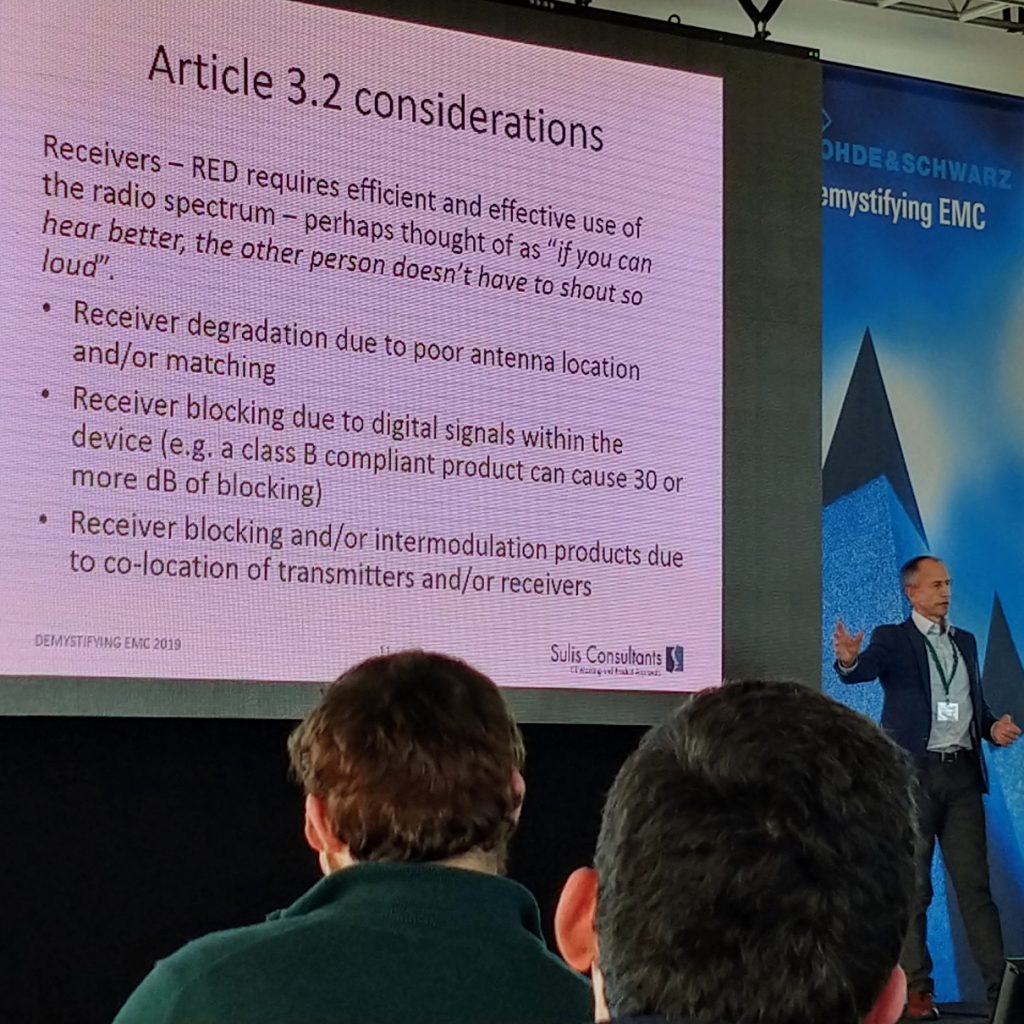
On 28th January Charlie Blackham presented “Radio performance issues when installing radio modules and collocating multiple radio transceivers” at Rohde & Schwarz Demystifying EMC 2019.
The presentation covered:
- Brief discussion of Radio Equipment Directive and what is “radio equipment”
- EMI coupling of clocks and other signals causing receiver blocking and reduced operating range
- Antenna inefficiency and how your antenna might not behave as the datasheet says
Full details of the program of 16 presentations is available here.
Some of the information covered is summarised below:

Antenna optimisation and receiver blocking
A number of digital devices are transformed into radio transceivers via the addition of a 3rd party radio module.
Figure 1: GSM/3G module installed in a netbook computer
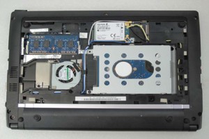
Whilst the module allows radio communication, performance may not be as good as expected for a number of reasons including:
- The digital device may have a number of clock harmonics that are low enough to pass Class B radiated emissions limits, but that does not prevent them from effecting co-located receivers within the system.
- The design of the antenna, its position within the unit and effect on co-located circuits and enclosures will all effect antenna performance.
These “receiver blocking” and “antenna optimisation” issues are discussed further below.
Camera Clock Harmonic in GSM receive band – passes radiated emissions, but will block GSM receiver – poorly designed product.
Camera Clock Harmonic in 3G smartphone, designed with receiver performance in mind to minimise blocking – well designed product.
Receiver Blocking
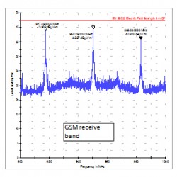
If we consider a GSM module with an external antenna connected via a short length of co-axial cable, then we can look directly at the electrical noise generated by the product that is picked up by the antenna and injected into the module receive circuit.
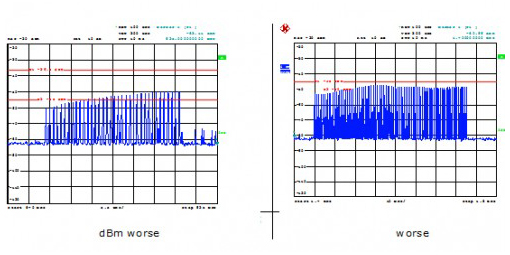
Figure 2: digital clock harmonics received via GSM antenna
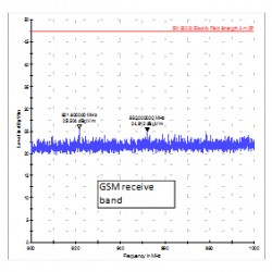
Looking more closely at the clock harmonic at 931.5 MHz, we can see the effect that this 69th harmonic of the 13.5 MHz clock has on the radio module using a Rohde & Schwarz CMU200:
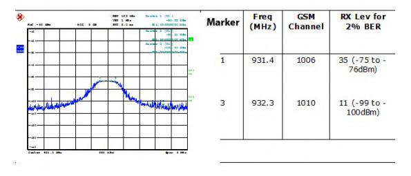
Figure 3: GSM receiver performance for blocked and non-blocked channels
We can see that a “blocked” channel coinciding with clock harmonic is 24dB worse than an “unblocked” one with no clock harmonic.
This corresponds to the receiver working on the unblocked channel at 15 times the distance it can operate on the blocked channel.
Since the GSM receive channel is allocated by the cellular basestaion and will be different in different locations and on different networks, the only way to ensure good performance is to minimise the level of blocking.
Antenna Optimisation
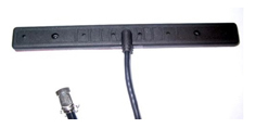
Whilst a product might be fitted with a connectorised dipole antenna such as the one shown in figure 4, how it performs when fitted to a device can be very different to how it performs in free space.
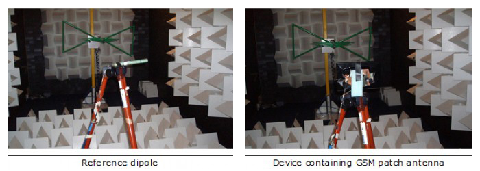
Figure 6: Antenna performance compared against reference dipole
Similar measurements can be made whilst rotating the product to build up a full picture of antenna performance.
In need of a consultation?
Get in touch with us today